
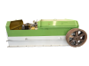
LD Series Pipe Cold Rolling Mill
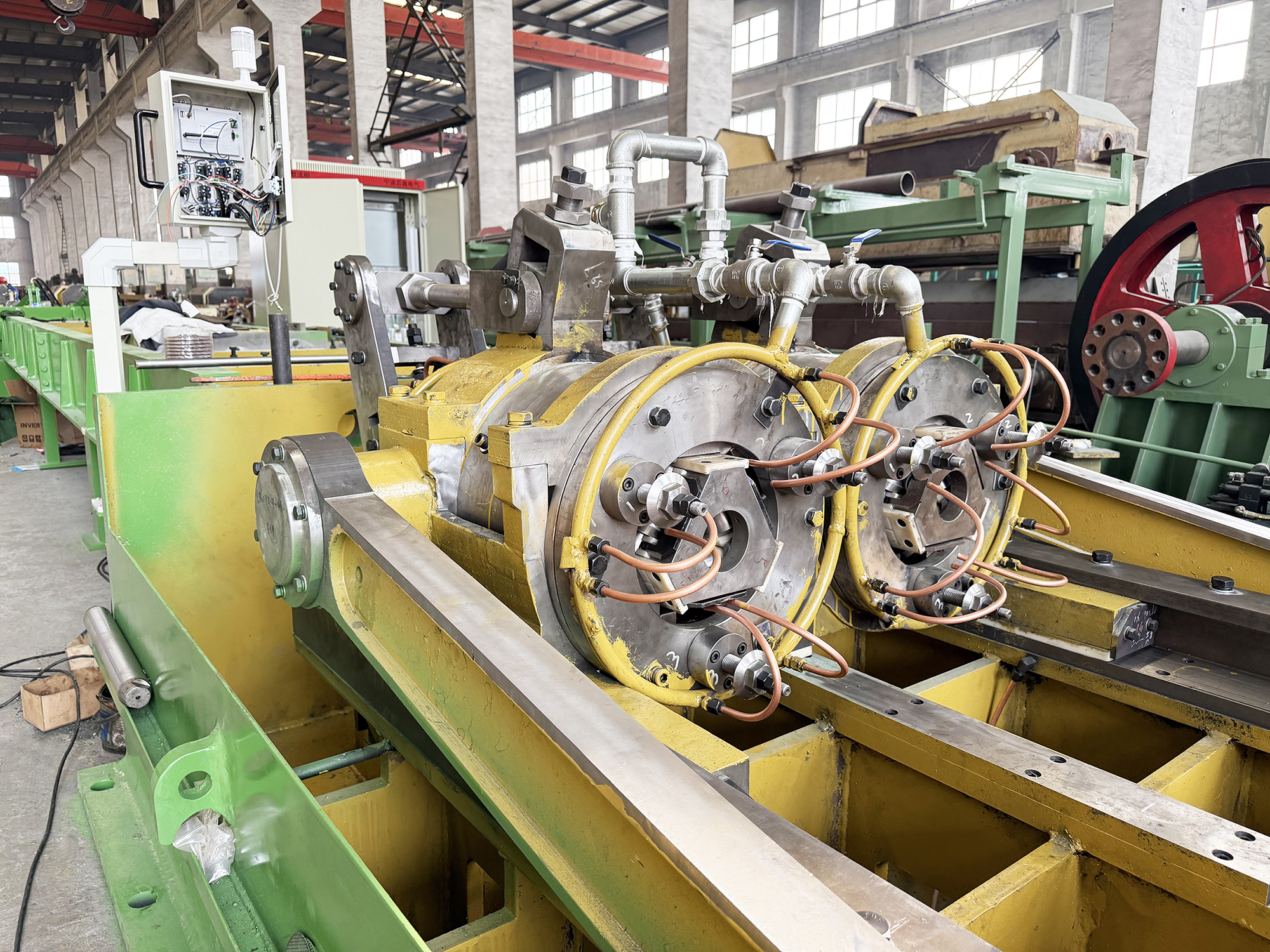
LD Series Pipe Cold Rolling Mill
.png)
.png?x-oss-process=image/resize,w_100/quality,q_100)
Compared with two-roll cold pilger mills, multi-roll cold pilger mills (such as three-roll and five-roll models) demonstrate significant advantages in machining accuracy and process performance. By adopting a multi-roll symmetrical layout (120° for three-roll or 72° for five-roll configurations), the tube material is subjected to more uniform multi-directional compressive stresses during the rolling process, resulting in superior dimensional accuracy and surface quality. Although multi-roll mills have smaller single-pass reduction rates in both diameter and wall thickness, they achieve more precise dimensional control. The three-roll cold pilger mill can produce ultra-precision thin-walled tubes with outer diameters as small as 3mm and wall thicknesses as thin as 0.1mm—a processing limit difficult to attain with two-roll mills. This exceptional processing capability makes multi-roll mills indispensable equipment for high-end applications such as minimally invasive medical devices and aerospace precision tubing.
Characteristics of Cold Pilger Mills
Capable of producing precision thin-walled tubes from carbon steel, bearing steel, low-alloy steel, stainless steel, titanium alloys, zirconium alloys, high-temperature alloys, copper-nickel alloys, copper-aluminum, and various non-ferrous metals.
Utilizes ring-shaped groove rolls for long-stroke rolling, featuring large roll rotation angles and extended working sections of the groove, increasing the deformation zone length. The curved mandrel enhances metal deformation uniformity, allowing for larger feeding amount and improved finished tube quality.
Employs a curved mandrel to reduce rolling pressure, ensuring uniform deformation of the billet. Each pass achieves high reduction rates and significant wall thickness correction, with evenly distributed rolling forces and reduced axial forces, enabling the production of tubes with minimal outer diameter and wall thickness deviations.
Main drive system adopts permanent magnet motors for energy efficiency and stability.
Rotary and feeding are controlled by servo motors, ensuring precise and reliable feeding amount with stepless adjustment, as well as stepless adjustment of rotation angles. Within one rolling stroke, the billet undergoes two rotations and one feeding (or two rotations and two feeding).
All gear pairs in the eccentric gearbox are manufactured using hard-tooth grinding processes, with gears meeting Grade 5-6 precision standards, ensuring smooth transmission, long service life, and low noise
Achieves extremely tight tolerances and superior surface roughness for both inner/outer diameters and wall thickness
No material loss in the process, resulting in high material yield
| No. | Parameter Name | Unit | LD Series Cold Pilger Mill Model & Specifications | ||||||||
| 1 | Model | LD8 | LD20 | LD40 | LD60 | LD90 | LD120 | LD180 | LD220 | LD320 | |
| 2 | Mill Operating Mode | Three Roller Fully Auto with Non-Continuous Feeding |
Three Roller Fully Auto with Non-Continuous Feeding |
Three Roller Fully Auto with Non-Continuous Feeding |
Three Roller Fully Auto with Non-Continuous Feeding |
Five Roller Fully Auto with Non-Continuous Feeding |
Five Roller Fully Auto with Non-Continuous Feeding |
Five Roller Fully Auto with Non-Continuous Feeding |
Five Roller Fully Auto with Non-Continuous Feeding |
Five Roller Fully Auto with Non-Continuous Feeding |
|
| 3 | Mother Tube OD | mm | Ø4~Ø10 | Ø10~Ø22 | Ø17~Ø48 | Ø32~Ø75 | Ø65~Ø114 | Ø65~Ø140 | Ø100~Ø190 | Ø133~Ø250 | Ø170~Ø330 |
| 4 | Mother Tube WT | mm | 0.3~1.5 | 0.5~2 | 0.5~3 | 0.8~6 | 1.5~10 | 1.5~12 | 3~15 | 4~16 | 3~20 |
| 5 | Mother Tube Length | m | 1~4 | 1~4 | 1~5 | 1~5 | 2~6 | 2~6 | 2~6 | 2~8 | 3~8 |
| 6 | Finished Tube OD | mm | Ø3~Ø8 | Ø8~Ø20 | Ø15~Ø45 | Ø30~Ø72 | Ø60~Ø108 | Ø60~Ø133 | Ø90~Ø180 | Ø120~Ø242 | Ø160~Ø320 |
| 7 | Finished Tube WT | mm | 0.1~1.3 | 0.3~1.5 | 0.3~2.5 | 0.5~5 | 1~8 | 1~10 | 2~13 | 3~15 | 2~18 |
| 8 | Finished Tube Length | m | ≈8 | ≈8 | ≈8 | ≈10 | ≈12 | ≈12 | ≈15 | ≈15 | ≈15 |
| 9 | Feeding Range | mm /stroke | 0.5~4 | 1~6 | 1~8 | 1~8 | 1~10 | 1~12 | 1~12 | 1~12 | 1~15 |
| 10 | Rotation Angle Range | degree | 0~72 | 0~72 | 0~72 | 0~72 | 0~72 | 0~72 | 0~72 | 0~72 | 0~72 |
| 11 | Rotary Feeding Type | Independent Servo Drive Continuously Working |
Independent Servo Drive Continuously Working |
Independent Servo Drive Continuously Working |
Independent Servo Drive Continuously Working |
Independent Servo Drive Continuously Working |
Independent Servo Drive Continuously Working |
Independent Servo Drive Continuously Working |
Independent Servo Drive Continuously Working |
Independent Servo Drive Continuously Working |
|
| 12 | Rotary Feeding Mode | Single Rotary Single Feeding |
Single Rotary Single Feeding |
Single Rotary Single Feeding |
Single Rotary Single Feeding |
Single Rotary Single Feeding |
Single Rotary Single Feeding |
Single Rotary Single Feeding |
Single Rotary Single Feeding |
Single Rotary Single Feeding |
|
| 13 | Roller Size | mm | Ø30.5 | Ø54, Ø70 | Ø90 | Ø131, Ø143 | Ø249, Ø268, Ø286 | Ø270, Ø286, Ø304 | Ø411, Ø455 | Ø455, Ø497, Ø515 | Ø631, Ø700 |
| 14 | Mainframe Stroke Speed | spm | 60~110 | 60~120 | 60~110 | 50~90 | 40~80 | 40~70 | 20~60 | 20~55 | 15~45 |
| 15 | Mainframe Travel Length | mm | 400 | 450 | 475 | 603 | 753 | 903.5 | 1206 | 1206 | 1506 |
| 16 | Main Motor Power | kw | 5.5 | 22 | 37 | 55 | 90 | 160 | 250 | 250 | 400 |

CONTACT US
Contact US
Product Information
Quantity
Unit
Piece
Support order samples, customization, wholesale direct, and complete payment. If the product you look for does not have corresponding customized content, pls fill out the form below to contact us, and we will reply ASAP.